PH - Test
Test objectives were as follows:
- Determine optimal injection pressures
- Hold stable combustion for at least 2 seconds at the designed chamber pressure
Test Stand
Test stand had 3 pressure transducers (one for each propellant line and one for the igniter combustion chamber). It also had a solenoid valve for each propellant line and a Rcexl Automatic Single Ignition coil for the spark plug. Controlling the solenoids and reading data from the sensors was an Arduino. The plumbing was almost identical to that of the budget bi-prop, with a single IPA tank pressurized by nitrogen for the igniter's fuel supply. Data was collected using a MatLab program and GUI.
Arduino, received data from three pressure transducers
Overview of the stand, nitrogen and oxygen bottle mounted at the back
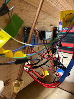
Relays and converter are visible for controlling solenoids
MatLab GUI plots pressure data. Also allows sensor calibration
Initial Challenges
The initial test campaign for the igniter revealed several major design flaws. First, the injector orifices directly opposed each other, causing IPA to enter the GOX line. This occurred as a result of the orifices directly opposing each other and the fact that the GOX orifice was so much larger than the IPA orifice. The location and size of the orifices, combined with closing the GOX solenoid valve before IPA solenoid upon igniter shutdown, allowed IPA to enter the GOX line. As one might expect, this caused significant damage to the GOX line when following tests occurred:
Combustion in GOX line resulted in damaged solenoids and pressure transducer.
can be observed, with small 1/4-32 spark plug starting ignition at the top.
Updated Design
It was clear that a redesign was needed. In the second design, the IPA line was moved to the location of the previous spark plug (top of the igniter) while the GOX line remained on the side. Additionally, the spark plug was positioned on the side of the igniter right at the point where the GOX and IPA would meet.
New igniter was shorter and had a different injector configuration


Old (left) - Note two opposing fluid lines
New (right) - Note IPA line perpendicular to GOX line
By changing the location of the orifices and the timing of the solenoid valves (with a GOX lead), the igniter performed much better. However, there was still a problem. The igniter, rather than achieving steady combustion, would "pop" 3 or 4 times.
If was eventually found that the injection pressure for each propellant was way too high. For a chamber pressure of 50psi, the injection pressures were as high as 200psi. This huge discrepancy was the result of an assumption made that the pressure drop across an orifice was around 100 to 150 psi, rather than 50% to 100% of the chamber pressure. Sure enough, at around 60psi GOX injection and 100psi IPA injection, stable combustion was achieved:
Post - Test
While this project was discontinued after its first few successful hotfires, future versions of the igniter would most likely replace the current spark plug with a surface gap spark plug. In the video above, the orange flash is actually the electrode of the spark plug melting away:
I thoroughly enjoyed this project and learned a ton about testing. In the future, I think it would be worth investing in nicer test stand hardware and also double checking design assumptions and geometries before throwing them on the stand. In all, I was very satisfied with the project's result.


Comments
Post a Comment